PACS Architecture: How It Works, Key Components, and Architecture Models

PACS (Picture Archiving and Communication System) architecture refers to the structural design of a system that stores, retrieves, manages, and distributes digital medical images across a healthcare network.
Imagine a world without PACS—chaotic film archives, slow image retrieval, and disconnected workflows. Thankfully, PACS architecture revolutionized medical imaging, becoming the backbone of modern healthcare.
Whether optimizing storage or integrating cloud solutions, I will help you explore the nuts and bolts of PACS architecture to keep your expertise sharp!
This guide covers PACS — Picture Archiving and Communication System — the medical imaging infrastructure used by hospitals and radiology departments to store, retrieve, and distribute diagnostic images.

What Is a PACS System?
A PACS (Picture Archiving and Communication System) is a digital healthcare solution that stores, retrieves, manages, and shares medical images, such as X-rays, CT scans, and MRIs. It eliminates the need for physical film and allows authorized users—radiologists, clinicians, and other providers—to access and review images from any location.
PACS integrates with imaging devices and electronic medical records (EMRs), streamlining image workflow, boosting collaboration, reducing costs, and improving patient care. Whether deployed on-premise or via the cloud, PACS enhances diagnostic speed, efficiency, and data security across the healthcare system.
What components are required for a PACS system
| Component | Type | Function |
|---|---|---|
| Imaging modalities | Hardware | CT, MRI, X-ray, and ultrasound scanners that capture and generate DICOM image files |
| DICOM gateway | Hardware / software | Receives DICOM studies from modalities and routes them to the correct archive or workflow destination |
| PACS archive | Software / storage | Stores, indexes, and manages DICOM objects; enables query and retrieval via C-FIND and C-MOVE or DICOMweb |
| QA workstation | Software | Reviews patient demographics and image quality before studies are committed to the archive |
| Reading workstation / viewer | Software | Provides radiologists with diagnostic tools — windowing, MPR, MIP, annotations — to interpret studies |
| PACS server | Hardware / software | Manages the workflow database, query/retrieve operations, and communication between all PACS components |
| Network infrastructure | Hardware | LAN and WAN connecting modalities, archive, server, and workstations; bandwidth and latency directly affect read performance |
| RIS integration | Software | Connects the Radiology Information System to PACS via HL7; delivers the Modality Worklist and routes completed reports back to the EHR |
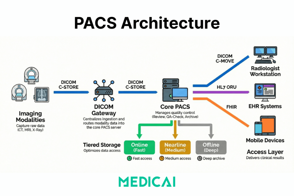
The PACS architecture typically consists of four key components: imaging modalities (devices that generate medical images), a secure network for image transmission, a workstation for interpreting and reviewing images, and archives for storing the images.
It replaces traditional film-based systems with digital methods, allowing for more efficient and accessible image management and improving workflow and patient care.
Image Acquisition
The PACS process begins by acquiring medical images from various imaging modalities, such as X-ray machines, MRI scanners, and CT scanners. These devices capture digital images, departing from traditional film-based methods.
Image Storage
Once acquired, the digital images are transferred to the PACS server for storage. PACS employs a secure, scalable database system to organize and store vast amounts of medical imaging data. This digital storage eliminates the need for physical film archives, saving space and reducing the risk of damage or loss.
Image Retrieval and Distribution
PACS systems enable healthcare professionals to quickly and efficiently retrieve stored images. This accessibility is crucial for timely diagnoses and treatment planning. Furthermore, PACS facilitates the distribution of images to authorized users across different departments or geographical locations, fostering seamless collaboration.
Viewing and Analysis
PACS provides advanced viewing and analysis tools, also known as DICOM viewers, for healthcare professionals. Radiologists and clinicians can access the images on dedicated workstations, laptops, or mobile devices, allowing flexibility and convenience. PACS and DICOM often include features for zooming, rotating, and annotating images, aiding in accurate diagnostics.
Integration with Electronic Health Records (EHR)
PACS integrates seamlessly with Electronic Health Records (EHR) to ensure a comprehensive patient record. This integration enables healthcare providers to access imaging data and patient medical history in a single centralized system, promoting a holistic approach to patient care.

How Does PACS Work? The Step-by-Step Workflow
PACS workflow follows a consistent sequence from imaging order to report delivery. Understanding each step explains where delays, errors, and integration failures originate — and where improvements have the most operational impact.
Step 1 — Order and Scheduling (HIS/RIS → Modality Worklist)
The workflow begins before any image is acquired. When a clinician orders an imaging examination, the order travels from the Hospital Information System (HIS) or Electronic Health Record (EHR) to the Radiology Information System (RIS) via an HL7 ORM message. The RIS registers the order, assigns an accession number, and writes a scheduled exam entry to the Modality Worklist (MWL) server.
The imaging modality — CT scanner, MRI, X-ray unit — queries the MWL server before each acquisition using the DICOM C-FIND operation. This query pulls the patient’s name, ID, accession number, and exam description directly into the modality, eliminating the need for the technologist to manually enter demographics. When the MWL connection is working correctly, the patient demographics in the resulting DICOM file are accurate and match the RIS record exactly. When it is broken, the technologist manually enters demographics, leading to transcription errors that cause downstream patient identity mismatches.
Step 2 — Image Acquisition (Modality → DICOM Gateway)
The modality acquires the study and packages the images as DICOM objects. Each DICOM file contains both the pixel data (the image itself) and a structured header with patient demographics, study metadata, acquisition parameters, and modality-specific tags. The modality sends these files to the PACS using the DICOM C-STORE operation — pushing each file to the PACS server’s Storage Service Class Provider (SCP).
In environments with multiple sites or legacy modalities that cannot connect directly to the PACS archive, a DICOM gateway sits between the modality and the archive. The gateway receives C-STORE transmissions, applies routing rules, and forwards studies to the correct destination — the local PACS, a cloud archive, or both.
Step 3 — Quality Assurance (QA Workstation)
Before studies are committed to the long-term archive, most PACS workflows include a QA checkpoint. A technologist reviews the study on a QA workstation to verify that patient demographics match the order, that image quality meets diagnostic standards, and that the correct protocol was applied. Studies that fail the QA check are rejected back to the technologist for correction or re-acquisition.
This step is the last opportunity to catch demographic errors before they propagate into the archive. A study committed to the archive with an incorrect patient ID requires a correction workflow — DICOM Patient Information Reconciliation (PIR) — to fix, which is operationally expensive. Investing in QA at this step is significantly cheaper than correcting errors after archiving.
Step 4 — Archiving (PACS Server → Short-Term and Long-Term Storage)
Approved studies are written to the PACS archive. Modern PACS systems use tiered storage: recent studies (typically the last 30–90 days) sit in online storage for fast retrieval, studies from the previous year or two sit in nearline storage with slightly slower access times, and older studies move to offline or deep archive. The PACS server manages the lifecycle rules that govern when studies migrate between tiers.
In cloud-native PACS deployments, this tiering maps directly to cloud storage classes — hot storage for active studies, cool storage for nearline, and archive-class object storage for long-term retention. The cost difference between storage tiers is significant: hot storage costs roughly 10–20 times as much per gigabyte as archive-class storage, making lifecycle management directly relevant to operating costs.
Step 5 — Prefetch and Priors Retrieval
When a radiologist opens a study on their reading workstation, the PACS does not simply display the current study in isolation. A prefetch workflow runs automatically — triggered when the exam appears on the radiologist’s worklist — and queries the archive for relevant prior studies. Relevant priors are defined by configurable rules: same modality, same body part, same patient, within a configurable time window.
Prefetch dramatically reduces the time the radiologist waits for prior studies to load. Without prefetch, the radiologist manually searches for priors at reading time, waits for the archive query, and waits again for the images to transfer to the workstation. With a well-configured prefetch workflow, relevant priors are already in the workstation’s cache when the radiologist opens the study.
Step 6 — Reading and Interpretation (Radiologist Workstation)
The radiologist reads the study on a diagnostic workstation or zero-footprint web viewer. Reading tools include window and level adjustment, zoom and pan, multiplanar reconstruction (MPR), maximum intensity projection (MIP), annotations, and measurements. For complex studies — cardiac CT, breast tomosynthesis, MR neuroimaging — the viewer must handle large volumetric datasets without latency.
This step is where the tradeoff between thick-client and thin-client architecture becomes operationally significant. Thick-client workstations process image data locally, enabling radiologists to interact quickly with large datasets but requiring managed endpoint hardware. Zero-footprint web viewers stream processed images from a server, making them accessible from any browser, but dependent on network quality and server-side rendering capacity.
Step 7 — Reporting (RIS → EHR Distribution)
After reading, the radiologist generates a report in the RIS or a dedicated reporting system. The signed report is distributed via HL7 ORU message back to the ordering clinician’s EHR and to the referring clinician’s system. In well-integrated environments, the clinician sees the report appear in the patient’s EHR record alongside a link that opens the images directly in a viewer — without requiring a separate PACS login.
When HL7 integration is incomplete or the interface engine between PACS and EHR is misconfigured, report distribution fails silently. The radiologist’s report exists in the RIS but does not reach the EHR. The ordering clinician must log in to a separate system to retrieve results—a workflow that delays clinical decisions and erodes the value of the integrated imaging infrastructure.
Step 8 — Long-Term Archive and Retention
Studies that have completed the active care cycle are moved to long-term archive in accordance with jurisdiction-specific retention requirements. In the United States, adult imaging studies are typically retained for 5–7 years, depending on state law; paediatric studies are retained until the patient reaches adulthood and the statutory minimum. Mammography studies have specific retention requirements under MQSA.
Long-term archive must remain queryable — a study archived 10 years ago must be retrievable in the same way as a study from yesterday. This is the primary argument for VNA-first architecture: a VNA stores studies in standard DICOM format independent of any PACS vendor, ensuring that studies archived under a previous system remain accessible after a PACS replacement without requiring a full data migration.
The complete PACS workflow in sequence
| Step | System | DICOM / HL7 operation | Output |
|---|---|---|---|
| 1 — Order and scheduling | HIS/RIS → Modality | HL7 ORM → DICOM C-FIND (MWL) | Scheduled exam on modality worklist |
| 2 — Image acquisition | Modality → PACS gateway | DICOM C-STORE | DICOM files transmitted to archive |
| 3 — Quality assurance | QA workstation | DICOM C-FIND / C-MOVE | Verified studies committed to archive |
| 4 — Archiving | PACS server → Storage tiers | DICOM Storage SCP | Studies indexed in short and long-term archive |
| 5 — Prefetch | PACS server → Workstation | DICOM C-MOVE / WADO-RS | Prior studies cached before reading |
| 6 — Reading | Radiologist workstation | DICOM C-MOVE / WADO-RS | Diagnosis completed |
| 7 — Reporting | RIS → EHR | HL7 ORU | Report delivered to ordering clinician |
| 8 — Long-term archive | PACS / VNA → Deep storage | DICOM Storage SCP | Studies retained per retention policy |
What PACS architecture models type exist, centralized, distributed, and web-based?
PACS architecture models type defines three things: where images live, where computation happens, and how users access studies. PACS architecture models type changes, bandwidth demand, latency sensitivity, and operational control more than feature checklists.
Centralized PACS architecture (client-server, thick-client)
Centralized PACS architecture keeps images and indexes on a central PACS server and archive, and thick-client workstations do heavy lifting on the endpoint. Centralized PACS architecture is suitable for single-site environments where LAN performance remains predictable, and reading occurs on managed workstations. Centralized PACS architecture pressure points show up in operational control because endpoint upgrades, GPU requirements, and workstation patch cycles expand as the reading footprint grows.
Distributed PACS architecture (multi-site gateways)
Distributed PACS architecture places storage, cache, or gateway nodes closer to each facility, then synchronizes studies to a central archive layer. Distributed PACS architecture reduces WAN strain for multi-facility networks because local reads hit local infrastructure more often, and sync jobs absorb cross-site transfer. Distributed PACS architecture trade-offs show up in operational control because increasing node count increases the monitoring burden, routing logic, and failure-isolation work.
Web-based PACS architecture (thin-client)
Web-based PACS architecture keeps most processing on servers and delivers viewing via a browser-based thin client. Web-based PACS architecture expands access across locations because endpoint requirements drop and deployment becomes simpler. Web-based PACS architecture tradeoffs show up in latency sensitivity and server-side capacity, because every interaction depends on network quality and backend scaling.
What tradeoffs exist between thick-client, thin-client, and distributed PACS architecture?
| Tradeoff dimension | Centralized (thick-client) | Distributed (multi-site) | Web-based (thin-client) |
|---|---|---|---|
| Bandwidth | Pulls large image datasets to the endpoint workstation — high LAN bandwidth demand, manageable on campus | Shifts cross-site transfers into scheduled sync windows — local reads hit local cache, reducing WAN load | Shifts processing to the server — endpoint bandwidth demand is low but server uplink and rendering capacity must absorb all sessions |
| Latency | Tolerates moderate WAN issues well within a campus LAN — poor performance degrades significantly over low-bandwidth remote connections | Reduces cross-site latency by keeping recent priors in local cache — remote reads of non-cached studies still depend on WAN quality | Fully exposes latency on remote reading sessions — every interaction depends on round-trip time between browser and rendering server |
| Operational control | Low node count — simpler to monitor, but endpoint GPU requirements, patch cycles, and workstation upgrades expand as reading footprint grows | High node count — each gateway or edge node adds monitoring burden, routing logic, and failure-isolation work to the IT team | Endpoint management is minimal — operational burden shifts to server-side capacity management, observability, and scaling |
| Upgrade path | Upgrades hit every endpoint workstation — coordinating rollouts across a large reading fleet is operationally expensive | Upgrades hit both the central archive and every edge node — more components to coordinate than centralized | Upgrades hit the server only — endpoints receive new functionality immediately with no local deployment required |
| Failure mode | Central server failure affects all users simultaneously — single point of failure unless high-availability architecture is in place | Failures isolate to a site more often — local cache allows continued reading even if the central archive is temporarily unreachable | Failures cluster around backend saturation and network degradation — all users are affected when server capacity or connectivity degrades |
Cloud-Based PACS Architecture extends web-based PACS architecture by moving core storage and services into a managed infrastructure while keeping DICOM ingestion and site connectivity under tighter control.
Cloud-Based PACS Architecture
Modern advancements have introduced cloud-native PACS architectures that enhance scalability, security, and accessibility:
- Cloud Platform: Handles long-term image storage, data flow management, and backend operations in a multi-tenant mode.
- Access Devices: Serve as gateways between local DICOM interfaces and cloud services. These devices host local storage and enable secure communication with the cloud platform.
- Cloud-based systems use technologies such as Kafka for data flow management, Memcached for caching services, and AWS S3 for image archiving.
PACS Storage: Online, Nearline, and Offline Tiers
PACS storage is not a single layer — it is a tiered system that balances retrieval speed against cost. Every DICOM study a healthcare organisation acquires must be stored, indexed, and remain retrievable for years or decades, depending on jurisdiction. Managing this at scale requires understanding how the three storage tiers work, how studies move between them, and what the cost and performance implications are at each tier.
Online storage — immediate access
Online storage holds the most recently acquired studies, typically covering the last 30 to 90 days, depending on the institution’s configuration. Studies in online storage are available for immediate retrieval — a radiologist opening a study from the current worklist pulls images from online storage with subsecond response times.
Online storage uses high-performance solid-state or high-RPM spinning disk infrastructure. It is the most expensive tier per gigabyte and the most operationally critical. A failure in online storage directly interrupts the reading workflow. For cloud PACS deployments, online storage maps to hot-tier object storage — Microsoft Azure Hot Blob Storage or AWS S3 Standard, for example, which is designed for frequent, low-latency access.
Nearline storage — fast archive
Nearline storage holds studies that are past the active reading window but still likely to be needed for comparison — typically studies from the previous one to three years. Retrieval from nearline storage takes seconds to minutes rather than milliseconds, which is acceptable for prior study access but not for active worklist reading.
Nearline storage uses lower-cost spinning disk arrays, tape libraries with robotic retrieval, or cloud cool-tier object storage. In cloud PACS environments, nearline maps to cool or infrequently accessed storage tiers — Microsoft Azure Cool Blob Storage or AWS S3 Standard-IA — which cost roughly 40–50% less per gigabyte than hot storage but charge a retrieval fee for access.
Offline storage — deep archive
Offline storage is the long-term archive for studies beyond the nearline window — typically older than three years. Retrieval from offline storage takes minutes to hours. This tier is used primarily for legal, compliance, and rare clinical lookups rather than routine reading.
Offline storage uses tape archives or cloud archive storage, such as Microsoft Azure Archive Blob Storage or AWS S3 Glacier Deep Archive. Archive-class storage costs roughly 90% less per gigabyte than hot storage, making it the cost-effective solution for the large volume of historical studies that must be retained but are rarely accessed.
How studies move between tiers
The PACS server applies lifecycle management rules — configurable policies that define when a study migrates from online to nearline and from nearline to offline. A common configuration might move studies to nearline after 60 days and to offline after two years. The PACS maintains an index of where every study lives so that when a retrieval request arrives, it knows which tier to query and can initiate the appropriate retrieval process.
In legacy on-premise PACS deployments, lifecycle management requires manual configuration of hardware tiers and significant upfront investment in each layer of infrastructure. In cloud-native PACS deployments, lifecycle rules are applied automatically through the cloud provider’s object storage lifecycle policies — studies move between hot, cool, and archive tiers without any hardware management.
How much storage does a PACS system need?
Storage requirements depend on modality mix, study volume, and retention period. The table below provides approximate per-study storage sizes for common imaging modalities:
| Modality | Approximate size per study | Notes |
|---|---|---|
| X-ray (CR/DR) | 10 – 30 MB | 2–4 images per study; smallest PACS storage footprint per study |
| CT scan | 150 MB – 1 GB | Wide range depending on protocol; multi-phase contrast studies toward upper end |
| MRI | 100 – 500 MB | Multi-sequence protocols increase size; functional MRI and spectroscopy larger |
| Ultrasound | 20 – 200 MB | Video loops significantly larger than still frames |
| Mammography | 200 MB – 1 GB | Digital breast tomosynthesis (DBT) toward upper end; highest storage cost per study in most departments |
| PET-CT | 500 MB – 2 GB | Fused PET and CT datasets; largest routine modality footprint |
High-Availability PACS Design
For robust performance, high-availability architectures use three-tier models:
Application Layer: Provides user interfaces for image viewing
Database Layer: Manages relational databases like Oracle™ for DICOM data storage.
Business Logic Layer: Supports service classes for storage operations.
VNA vs PACS: Understanding the Distinction
While PACS focuses on the storage and accessibility of medical images, it’s essential to distinguish it from Vendor Neutral Archives (VNA). PACS primarily deals with the workflow and viewing aspects of medical imaging, providing tools for image analysis and collaboration.

On the other hand, VNA emphasizes the long-term storage and management of medical data, aiming for format neutrality and interoperability. PACS and VNA create a comprehensive ecosystem, ensuring the seamless integration and accessibility of medical imaging data throughout its lifecycle.
Advantages and Disadvantages of PACS Software in Medical Imaging
Advantages
- Efficiency Boost: PACS systems significantly enhance the efficiency of medical imaging workflows, allowing for quick retrieval, viewing, and distribution of images.
- Cost Savings: The transition from film to digital reduces costs associated with film and physical storage space. It also minimizes the risk of lost or damaged films.
- Enhanced Collaboration: PACS facilitates collaboration among healthcare professionals by enabling the sharing of images and diagnostic information across departments and locations.
Disadvantages
- Initial Implementation Costs: The upfront costs of implementing a PACS system, including hardware, software, and training, can be substantial.
- Learning Curve: Healthcare professionals may require time to adapt to the new digital workflow, which could potentially impact productivity during the initial stages.
- Integration Challenges: Ensuring seamless integration with existing systems, including Electronic Health Records (EHR), can present challenges that must be addressed for optimal functionality.

Medicai vs Traditional PACS: Technical Architecture Comparison
The distinction between Medicai and traditional on-premise PACS systems is architectural, not cosmetic. Traditional PACS systems were designed in an era of single-site, single-vendor deployments — their core assumptions about where data lives, how it is accessed, and how systems communicate are structurally different from a cloud-native platform built on modern API standards.
The table below maps the specific technical differences across seven dimensions:
| Dimension | Traditional on-premise PACS | Medicai Cloud PACS |
|---|---|---|
| Infrastructure | On-premise server hardware requiring capital expenditure, physical data centre space, and in-house maintenance | Built cloud-native on Microsoft Azure with geo-redundant storage across multiple availability zones — no on-premise server required |
| Image ingestion protocol | DICOM C-STORE via a locally configured PACS server — requires static IP addressing and firewall port configuration at each site | DICOMweb STOW-RS over HTTPS — modalities push studies to the cloud archive without requiring inbound firewall ports or static IP configuration |
| EHR integration method | HL7 v2 interface engine — requires separate middleware licensing, ongoing maintenance, and manual retesting after every system upgrade | HL7 FHIR APIs natively — connects to Epic, athenahealth, and AdvancedMD without interface engine middleware, reducing integration maintenance cost |
| Viewer delivery | Thick-client workstation software installed and maintained on each reading endpoint — GPU and storage requirements managed per device | Zero-footprint browser-based viewer — studies open in any modern browser on any device with no local software installation or endpoint GPU requirement |
| Scaling model | Vertical scaling — adding capacity requires hardware procurement, installation, and downtime for server reconfiguration | Horizontal elastic scaling on Azure — storage and compute scale automatically with imaging volume, with no downtime and no hardware procurement cycle |
| Disaster recovery | Requires a secondary off-site backup infrastructure — typically a separate tape library or remote server — with manual failover procedures | Geo-redundant replication across Azure availability zones — automatic failover with no secondary hardware investment and no manual intervention |
| Data portability | Data may be stored in vendor-proprietary formats — extraction at contract end requires vendor cooperation and may incur migration fees | Standard DICOM format stored in a decoupled VNA layer — data is accessible via DICOM C-MOVE or DICOMweb WADO-RS at any time, independent of the viewing application |
Medicai’s architecture is designed for the specific constraints of distributed healthcare networks — imaging centres with multiple sites, teleradiology groups reading remotely, and hospital systems consolidating legacy PACS infrastructure into a single cloud archive. The FHIR-native integration layer means that adding a new EHR connection does not require a new interface-engine project — only an API configuration. The DICOMweb ingestion layer means that connecting a new modality at a new site does not require on-site server installation — it requires pointing the modality’s DICOM send destination at the Medicai STOW-RS endpoint. Both changes reduce the IT overhead of expanding a multi-site imaging network, turning a months-long infrastructure project into a configuration task.
Frequently Asked Questions About PACS Architecture
What is PACS architecture?
PACS architecture is the structural design of a Picture Archiving and Communication System — the arrangement of hardware and software components that determines how medical images are acquired, transmitted, stored, retrieved, and displayed across a healthcare network. PACS architecture defines three things simultaneously: where images physically live (on-premise servers, hybrid edge nodes, or cloud object storage), where image processing happens (at the endpoint workstation, on a central server, or in the cloud), and how clinicians access studies (thick-client workstations, zero-footprint web browsers, or mobile applications). The architecture model chosen — centralized, distributed, or cloud-native — determines the system’s scalability, latency profile, disaster recovery capability, and total cost of ownership over a 7-to-10 year contract cycle.
What does PACS stand for?
PACS stands for Picture Archiving and Communication System. Each word describes a core function: Picture refers to digital medical images such as X-rays, CT scans, MRIs, ultrasounds, and mammograms stored in DICOM format; Archiving refers to the structured, indexed storage of those images across tiered storage layers for immediate and long-term retrieval; Communication refers to the transmission of images between imaging devices, storage systems, reading workstations, and clinical systems such as EHR and RIS; and System refers to the integrated software and hardware infrastructure that manages all four functions under a single coordinated workflow. The term was formally introduced in the early 1980s and became the standard terminology for medical imaging infrastructure following the adoption of the DICOM standard in 1993.
What are the main components of a PACS system?
A PACS system consists of eight components working together: imaging modalities (CT, MRI, X-ray units that generate DICOM files), a DICOM gateway (routes studies from modality to archive), a PACS archive (stores and indexes DICOM objects), a QA workstation (reviews studies before archiving), a diagnostic reading workstation or zero-footprint viewer (the radiologist’s interpretation tool), a PACS server (manages the workflow database and query/retrieve operations), network infrastructure (LAN and WAN connecting all nodes), and a RIS integration layer (connects scheduling, Modality Worklist, and report distribution via HL7). The absence or failure of any single component interrupts the imaging workflow — the PACS is only as reliable as its weakest integration point.
What is the difference between PACS and DICOM?
PACS and DICOM are not the same thing — DICOM is the standard, and PACS is the system that uses it. DICOM (Digital Imaging and Communications in Medicine) is the international standard that defines how medical images are formatted, stored, and transmitted — it specifies the file structure of each image, the metadata tags embedded in the header, and the network protocols (C-STORE, C-FIND, C-MOVE, WADO-RS) used to send and retrieve images between systems. PACS is the software and hardware infrastructure — the archive, server, viewer, and workflow engine — that implements DICOM to manage medical images in a clinical environment. A PACS must be DICOM-compliant to receive images from scanners, share images with other systems, and ensure long-term accessibility. DICOM compliance without a PACS would be a file format with no infrastructure to manage it; a PACS without DICOM compliance would be a proprietary silo unable to exchange data with any other system.
How does PACS connect to EHR?
PACS connects to EHR through two primary interface layers. The first is HL7 messaging: when a clinician creates an imaging order in the EHR, an HL7 ORM message travels to the RIS, which writes the scheduled exam to the Modality Worklist — the mechanism that pre-populates patient demographics on the scanner before acquisition. When the radiologist completes a report, an HL7 ORU message carries the signed report from the RIS back to the ordering clinician’s EHR record. The second layer is image access: in legacy deployments, the EHR displays the report text but images require a separate PACS viewer login. In FHIR-native deployments, the EHR launches the DICOM viewer in context — the clinician clicks a link in the patient’s EHR record and the relevant imaging study opens immediately in a zero-footprint browser viewer without a separate authentication step. Medicai connects to EHR systems including Epic, athenahealth, and AdvancedMD via HL7 FHIR APIs, embedding DICOM image access directly within the EHR interface and eliminating the separate viewer login.
How do PACS systems support multi-site imaging practices?
PACS systems support multi-site imaging through distributed architecture — placing storage nodes, DICOM gateways, or edge servers at each facility while synchronising studies to a central archive. Each site’s gateway receives studies from local modalities using DICOM C-STORE, stores them in a local cache for fast access, and replicates them to the central archive for enterprise-wide availability. Radiologists at any site — or reading remotely — can query the central archive for any study across the network using DICOM C-FIND and retrieve images via C-MOVE or DICOMweb WADO-RS. Cloud-native PACS platforms extend this architecture by eliminating the on-premise central archive entirely — each site connects its DICOM gateway to a cloud storage layer that all sites share, reducing infrastructure at each location to a single gateway device and moving the synchronisation, redundancy, and disaster recovery functions to the cloud provider’s managed infrastructure.


Related Articles


Lets get in touch!
Learn more about how Medicai can help you strengthen your practice and improve your patients’ experience. Ready to start your Journey?
Book A Free Demo